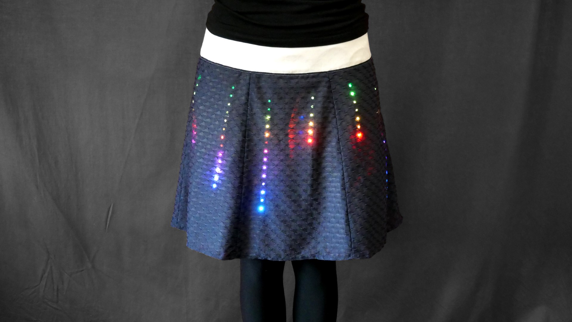
Addressable LEDs strips are a great and easy way to add complex multicolor light effects to any sort of object. Inspired by skirt projects from Make: authors Debra Ansell and Becky Stern, this project integrates 120 LEDs into a skirt while aiming to make it both as shiny and as wearable as possible. The LEDs are installed only at the front of the skirt to allow the wearer to sit down or use the restroom without potentially breaking the electronics. The LEDs and cables are completely removable for washing.

This article appeared in Make: Vol. 77. Subscribe today to get more great projects delivered to your mailbox.

The sewing was done by my wonderful girlfriend, Sabine. She has been sewing her skirts and dresses for decades now and creating her own sewing patterns. But the LED integration can be adapted to many other patterns, and we’ve added some tips for sewing your own. For this you’ll need some experience in sewing and pattern construction.

But you can also add these LEDs to an existing skirt — maybe one you don’t wear anymore — and add a semi-transparent fabric on top to get the same diffusion effect.

All electronics are hidden either in the skirt or in a pocket at the back, so the skirt appears as normal as possible when the LEDs are switched off. By adding a 6-axis accelerometer/gyroscope, we can trigger effects by movement or rotation in any direction, so there are many options to add unique lighting patterns to the LEDs in the future.

Building this skirt will teach you the usage of addressable LEDs in a simple matrix arrangement (6×20), and you will get a lot of attention wearing it. This is especially the case in school environments (e.g., for STEM teachers) to motivate kids doing LED projects and coding.

Uploading new code to the microcontroller is very easy, so you can continue to learn and improve your coding skills by adding new light effects.

Project Steps

CHOOSE YOUR FABRICS

The skirt itself consists of 3 layers:

OUTER LAYER: Blue top layer of semi-transparent polyester (above), for diffusion. The darker the color, the better it hides the LEDs when switched off. Some structure in the textile gives a nice additional diffusion effect.

MID LAYER: White cotton holding the LEDs and Velcro and guiding the cable. Also used for the waistband.

INNER LAYER: White lining fabric (polyester) to reduce resistance, especially while walking, so the mid layer is less folded.

SEW THE SKIRT

A panel skirt design based on 6 panels is attached to a thick waistband. The waistband lays flat and close fitted on the waist. There’s a zipper on the side. The pocket for the electronic stuff is attached to the waistband on the back of the skirt.

A panel skirt design is a good choice for this project; it’s easier to handle smaller pieces of fabric while preparing them for the LEDs. The outer layer should be about 1cm longer than the mid and inner layers, to hide the white fabric at the skirt’s hem when walking.

VELCRO, CABLE SLOT, AND POCKET

For fastening the LED strips to the mid cotton layer, you’ll cut 24 pieces of Velcro 2cm×1cm. The soft, fuzzy “loop” side is sewed to the mid layer, 4 Velcro pieces per LED strip. Using the soft side here is important to avoid scratching the fabric during washing.

Depending on the length of your skirt, you can decide how many LEDs you want to integrate. We used 20 LEDs per strip, so each strip is about 33cm long. Two Velcro strips are placed at top and bottom, the other two in between (under the 7th and 13th LEDs, in our case). You can use the strip as a reference for positioning the Velcro on the fabric. We attached the Velcro before assembling the full skirt, but it’s also possible to add it afterward if you use an already existing skirt.

The waistband is designed as a dual-layer white cotton structure with access from the mid layer to hide and guide the cables to the back. This also includes the pocket for the electronics and battery at the back, which has a buttonhole to access the cable from the inside. Small black snap fasteners fix the two cotton layers at the bottom to hold the cables in place.

As mentioned, depending on the skirt size, the number of strips and LEDs per strip may vary. To keep the wiring simple, the easiest way is to use a serpentine layout, so every output of a strip is connected to the input of the next strip. This allows the controller to drive all strips with only one I/O pin. The only drawbacks are additional connections at the skirt’s hem, and a zigzag placement for the strips, which can be easily compensated later in the code. Be sure you can hide these connections at the hem, either by a closure such as snaps, or a masking fabric layer.

If you want to avoid the hem connections, you can wire all inputs at the top separately and use multiple I/O pins on the microcontroller. But then you’ll have to route 5 more wires to the pocket.

Before installing anything to the skirt, the full LED arrangement can be pre-soldered. Wire length depends on your skirt size; add some spare length to account for movement. To secure and strengthen the connections, add heat-shrink tubing at the top of each strip.

At this stage, I’d highly recommended testing the LED strips with some sample code using the NeoPixel or Fast-LED library, to check your wiring before assembling the skirt. This can be done by following Adafruit’s great NeoPixel guide for the QT Py board.

Next, attach the rough “hook” side of the Velcro to your LED strips to line up with the Velcro on the skirt panels. Just cut away 2cm sections of the adhesive backing on the strips, and stick the Velcro to the adhesive.

ATTACH LEDS TO SKIRT

Place the LED strips on their desired positions and fasten with the Velcro. Route the cables through the double-layer waistband, and the guide the wires at the skirt’s hem in the closure.

CONTROLLER AND POWER SUPPLY

Connect the electronics as shown in the wiring diagram. The LED strip’s signal wire is soldered to pin A3 of the QT Py board. The 6-axis IMU sensor is connected via the short STEMMA/Qwiic cable.

The cable connectors that are originally pre-soldered to the LED strips can be reused to make it easier to unplug and remove the electronics from the skirt for washing. This way, no additional connectors are necessary.

To power the QT Py, you can use a standard USB power bank. 5000mAh seems to be more than enough for a full day’s use if you’re not using effects that light all the LEDs at the same time. The power bank and the QT Py and sensor nicely fit into the pocket at the back of the skirt. Plugging the QT PY’s USB into the power bank will power up the LEDs.

PROGRAMMING

You can use either CircuitPython or Arduino IDE to program the QT PY board. We used Arduino IDE in combination with Visual Studio Code and PlatformIO, so that we could include a special library which can easily divide an LED strip into multiple segments to control them as if they were wired as a single strip. It generates “virtual NeoPixel strips” so you can directly use existing lighting effect examples and libraries that are widely available for Neopixel LEDs.

Let’s take a look at the code. To show the use of the 6-axis sensor, we’ll look at the “bouncing ball” animation effect. Other effects like “meteor rain” or “fire” — and all future examples — are available at this project’s Github repository.

At the start of the code , libraries for the LSM6DSO32 sensor and the LEDs are included. Also, the QT Py’s pin A3 is defined as LED output as described above. If you have a different LED arrangement or number of strips, you can change MAXPIXELS and NSTRIPES accordingly.

Lines 15–20 define the virtual strips with a start and end pixel for each strip. For example, vNeo1 is the first strip of LEDs, with the start pixel 19 and the stop pixel 0 to address it from bottom to top, even if the signal comes from the top side. Because of the serpentine layout, vNeo2 as the second strip is oriented in the opposite direction, so start pixel is 20 and stop pixel is 39.

Line 23 defines an array bballs[] of the type npBouncingBall objects and assigns it to the different virtual strips. This is the effect object coming from the np.BouncingBall.h library.

After declaring the used variables, the sensor and LEDs are initialized in the setup() function. Sampling rate and range for the accelerometer are also set and can be changed here if needed.

PROGRAMMING continued

In the main loop(), line 57 updates the sensor data and the array diff[] is calculated as the absolute difference between the last acceleration sample and new sample for all three axes. We’re only interested in the acceleration change and don’t care about the static offset value based on the gravitational acceleration. Using all three axes also makes the calculation independent from the orientation of the QT Py board in the skirt pocket, so we don’t have to worry about that. Line 68 updates the effect continuously. If the effect with the shortest delay has finished, line 70 checks for a new trigger based on the sum of the axis’s differences and the previous defined motion threshold. If the threshold was hit, the effects are restarted on all bouncing balls. The code shown here changes the color continuously during the effect; if you prefer fixed colors, you can uncomment lines 72 and 78. This changes the color only for every new bouncing effect cycle.

Of course, this is a simple example of motion triggering because it’s using all the axes; you can trigger the effect by jumping, spinning, starting to run, whatever. If you prefer a single-axis trigger, you can fix the orientation of the sensor in the skirt pocket (or you can determine the orientation by software using the g-offset and doing some coordinate transformation to find the true z-axis).

UPLOAD THE CODE

To flash the code to the QT Py microcontroller, just follow Adafruit’s guide. There you’ll also find all the information you need if you want to use CircuitPython instead of Arduino IDE.

FLASH IT AND FLAUNT IT

The skirt is a great eye-catcher and attracts lots of attention and smiling faces. Above shows a sequence of the bouncing ball effect, but the video is so much better.

Below shows the fire and meteor effects that are also available at the Github repository. You can see them in the video too.

There are many further optimizations and modifications possible, and some are already in development. Just for starters, you could:

• Use the gyro for rotation-triggered effects

• Use the double-tap detection engine of the sensor to switch between effects

• Use the built-in pedometer to sync the effects with your steps

• Add backside LEDs for 360-degree effects (only for showcases, don’t sit on them!)

• Extend the LED strips for long skirts

Conclusion

There’s a good discussion going at my Hackaday.io project page, and all future source code will be uploaded to the Github repo, so it will be easy to share and contribute — your ideas are highly welcome. Using an ESP32 and syncing multiple skirts with WLED also could be a lot of fun!