Photo by Hep Svadja
Read articles from the magazine right here on Make:. Don’t have a subscription yet? Get one today.

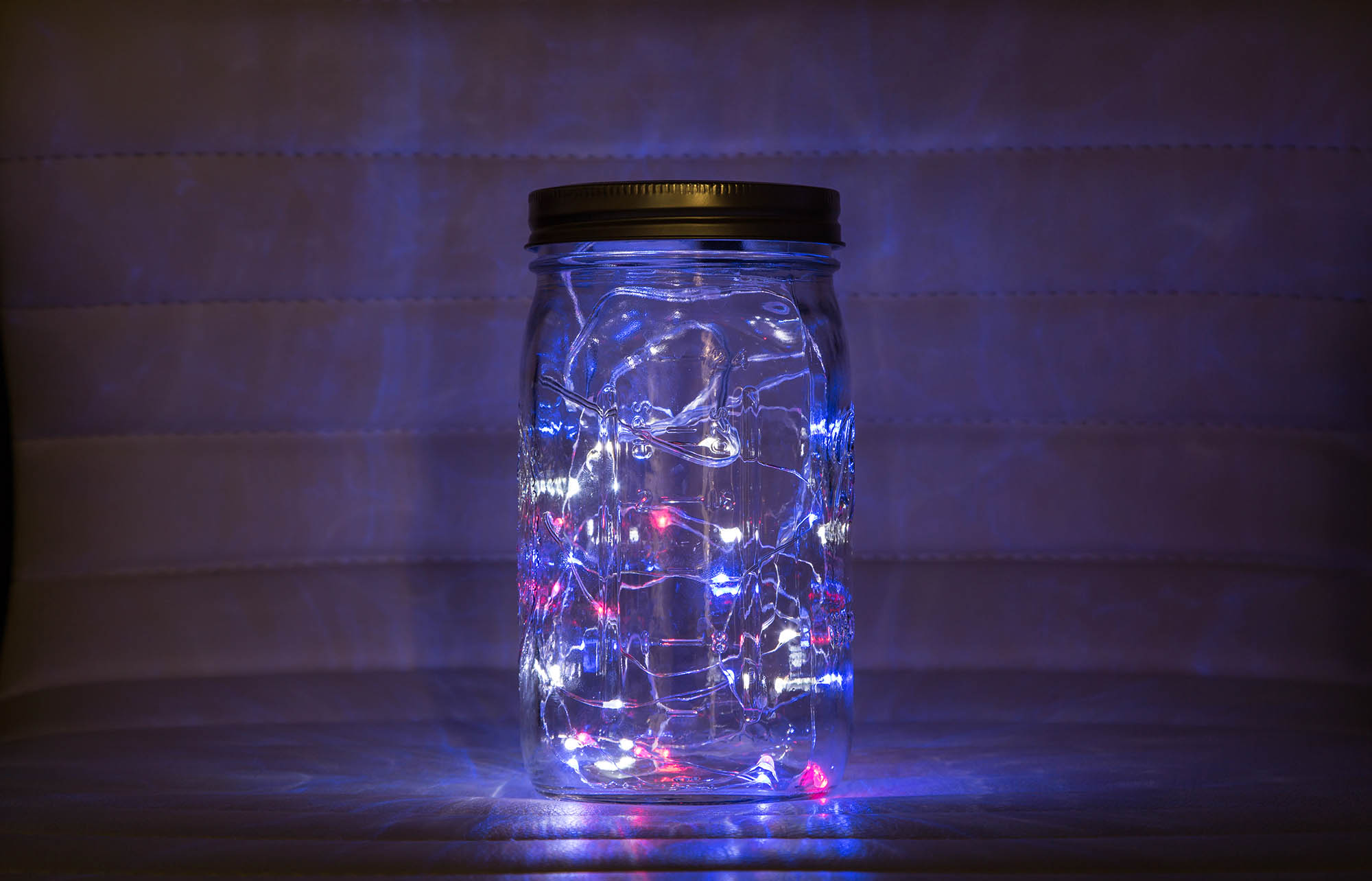
This project is an Arduino variant of the Pimoroni firefly light project, made patriotic for the Fourth of July. Basically you place three strings of battery-powered LEDs into a glass jar and use a microcontroller to sequentially fade the light strands — first red, then white, and finally blue, before repeating the series. The fade process repeats for as long as the microcontroller has power.

When I discovered the project, I thought it was really cool, but they threw a lot of hardware (a Raspberry Pi, two HATS, and a battery) into the solution, so I wanted to see if I could build something with fewer parts and for less money. This version of the project uses an Arduino-compatible board (you could use most any Arduino for this project), a battery module, and a battery.

Project Steps

Build the Lithium Battery Backpack Add-On

To enable the use of a SPST toggle switch to power the board on and off, use the utility knife to cut the trace connecting the two holes with the white box around them on the top right side of the Adafruit Pro Trinket LiIon/LiPoly Backpack Add-On (Figure A). Severing this trace disconnects the board’s power output, but once you connect a switch between those two holes, you’ll be able to control power to the Trinket board.

Figure A. Photo by Sydney Palmer

Solder the included headers to the Backpack Add-On. The header pins connect to the three holes in the upper-left corner of the board. Insert the headers through the board from the bottom with the black plastic part flush against the bottom of the board. The easiest way to do this is to insert the header pins in a breadboard, then mount the board on top for soldering (Figure B).

Figure B. Photo by Sydney Palmer

Wire and Solder the Toggle Switch

Cut two short lengths of wire, then strip the ends and solder one end of each wire to the switch (Figure C).

Figure C. Photo by Sydney Palmer

Finally, solder the open wire ends to the two switch holes where you cut the connecting trace (Figure D). Since the hardware will be bumped around in the glass jar, I placed heat-shrink tubing around the solder connections to protect them from being shorted out.

Figure D. Photo by Sydney Palmer

Solder the Backpack Add-On onto the Pro Trinket

The battery board mounts to the Battery, Ground, and USB 5V pins in the upper-right corner of the Trinket, as shown in Figure E.

Figure E. Photo is courtesy of Adafruit

Figure F shows the completed board assembly. To protect the USB connector on the Trinket board, I also placed a small piece of electrical tape on top of the board’s USB connector. It’s visible in Figure H.

Disassemble the Light Strand Units

Each strand comes with a battery pack and switch, but since we’re driving them all from the Trinket, you won’t need those parts.

For the Adafruit color LEDs, use a Phillips screwdriver to remove the screws from the battery case and open the case. The LED strand connects to the switch and battery contacts as shown in Figure G. Make note of which wires are connected to the battery’s positive (+) and negative (–) terminals. In my case, the contact in the left battery slot connects to the battery’s positive (+) terminal and the one in the right connects to the negative (–) terminal. I could tell this because the case was embossed with little + and – signs.

Figure G. Photo by Sydney Palmer

Next, cut the wires. If they aren’t coated in a way to make it easy to tell the difference between the two, quickly tie a knot in the negative wire. (“Knot” = negative. Get it?) That way you’ll know which is which.

Solder the LED Strands to the Trinket Board

Solder the wires to the appropriate pins on the Arduino Pro Trinket board. For each of the three strands, solder the negative (–) wire to one of the two GROUND pins (two to one pin and one to the other) in the lower-left corner of the board (see Figure E). Solder each strand’s positive (+) wire to pins 9, 10, and 11, one strand to each pin.

Plug the lithium polymer battery into the LiIon/LiPoly Backpack Add-On.

Download the Code

Connect the Trinket to your PC using a USB cable. Download the project’s compiled code and upload it to the Trinket. You can find complete directions on how to set up your Arduino development environment and deploy compiled code in the Trinket tutorial.

Mount it All in a Jar

You could just stuff the whole contraption into the jar — letting the hardware sit at the bottom. To charge the battery, or flip the switch, you’d have to pull the whole assembly out of the jar and put it back when you’re done.

However, the Adafruit lights are rather small and the strand is short, so the hardware stands out more prominently. The Mason jar implementation provides an interesting option for mounting the hardware. I drilled some holes in the lid, and, using two standoffs and screws, mounted the hardware to the underside of the lid. I then used two-sided tape to adhere the battery to the lid underneath the microcontroller (see Figure H). With this approach, you simply remove the lid to charge the battery or flip the switch, reducing stress on the assembly.

To operate, just turn it on and close the lid. You’re done!