Edge-lit displays typically consist of an etched sheet of acrylic, with one edge embedded in an opaque base containing a light source. The light diffuses through the acrylic to make the etchings glow. Different colors applied around the edge will blend smoothly inside; you can see this effect in my Edge-Lit LED Rainbow project in Make: Volume 69.

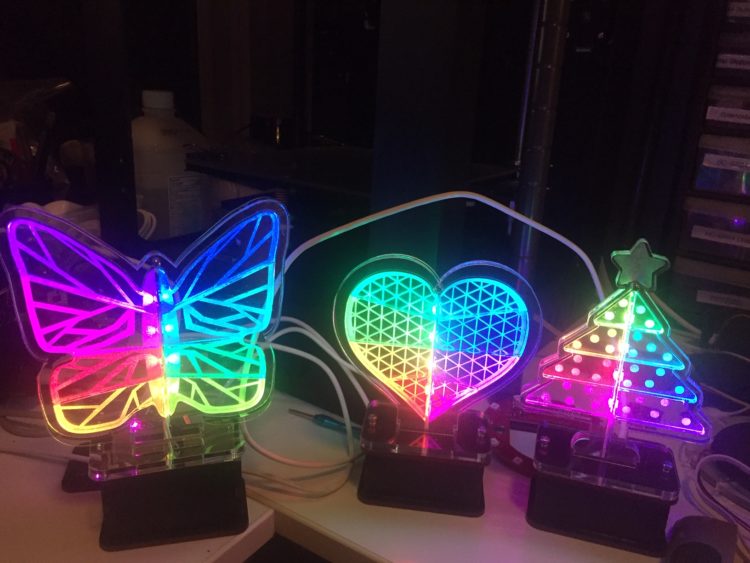
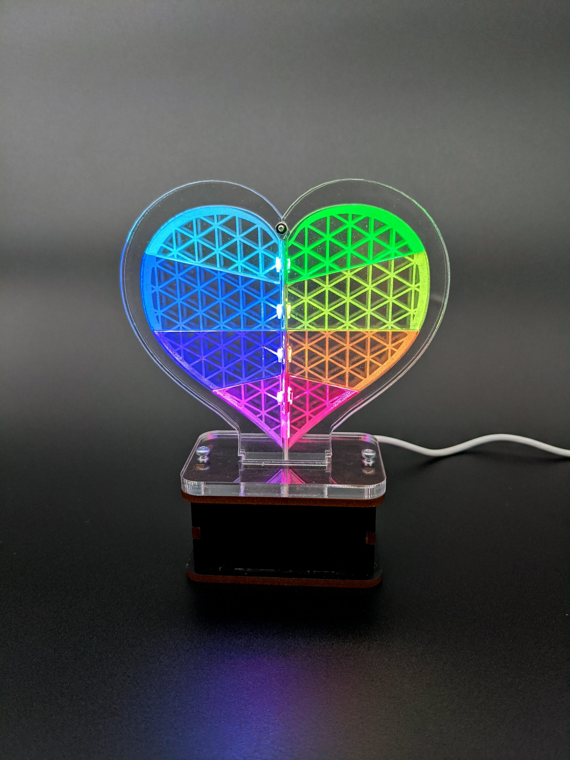
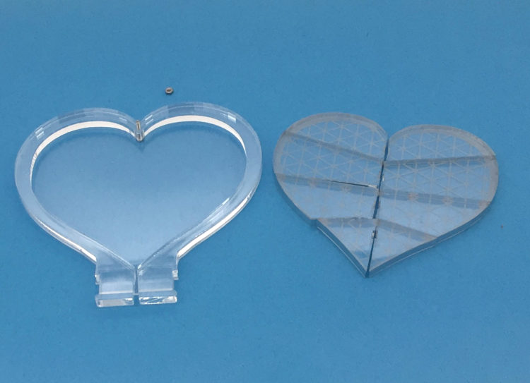
My new project takes a different approach to edge lighting, by cutting the acrylic into jigsaw-puzzle-like sections and embedding the light source between the pieces. This technique makes the shape appear to glow from the inside out. Illuminating each piece with its own color creates sharp boundaries for an unusual effect that’s great for dynamic, colorful animations. If you do your own laser cutting you can make it for 30 bucks.
Here I’ll show how to build an inner-glow heart, in plenty of time for February gift giving (hint hint). I also provide two other designs, and you can easily customize this project to create your own.
 A), using the template in WoodPieces.svg (download the full set of
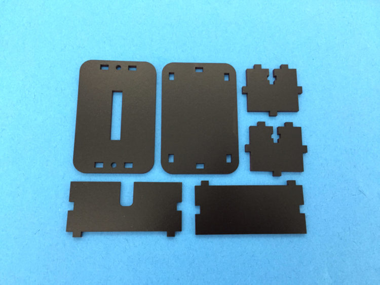
 ). Don’t glue the top, as it needs to be removable to place the microcontroller inside.
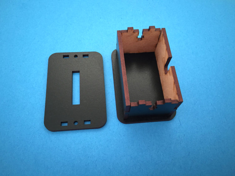
 ). There’s also a ¼” acrylic base to support this assembly.
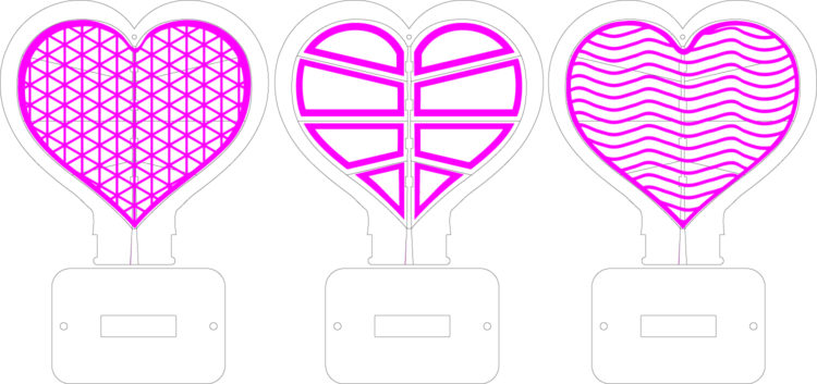
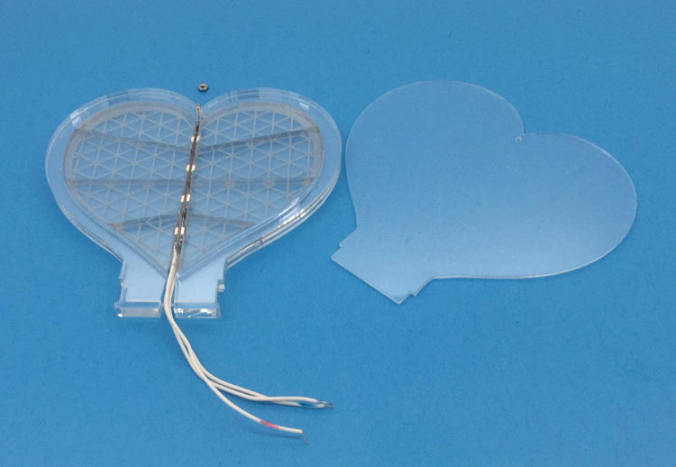
 ). To provide strain relief, cover the solder joints with a bit of heat-shrink tubing.
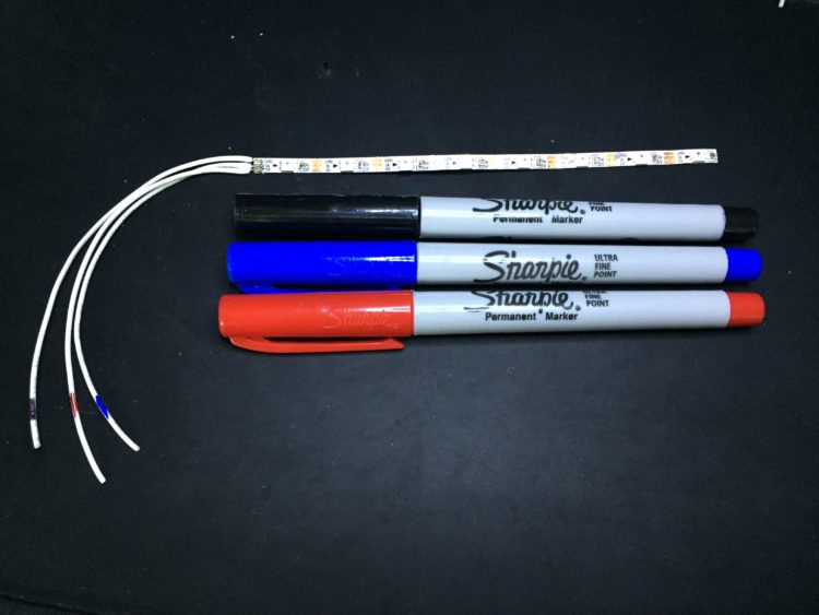
 E).
E).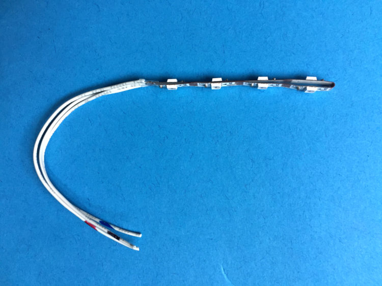
 F).
F).
 G).
G).
 ).
).
 ).
).
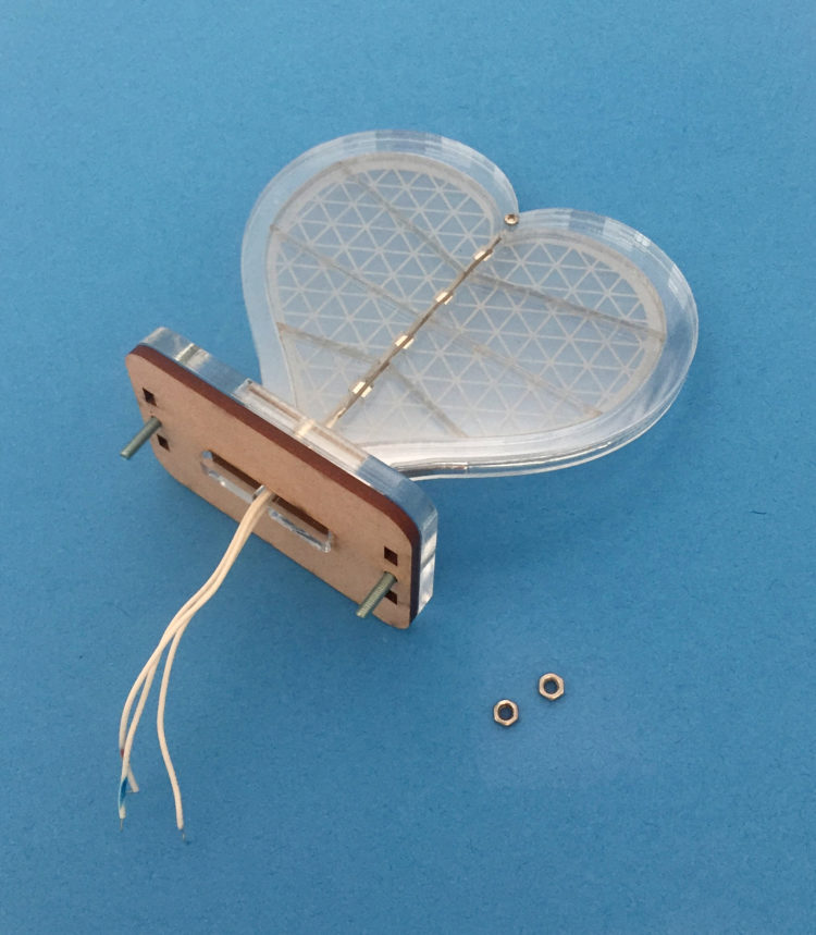
 ). The middle tab has a slot in the center; you’ll need to squeeze the edges together make it fit. Don’t force it, just squeeze gently and wiggle the base until it slips over the tabs.
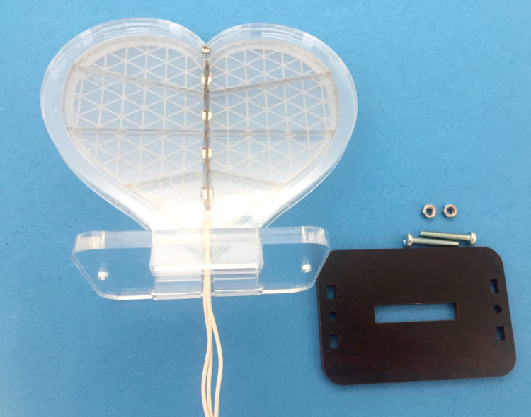
 ).
).
 L).
L).
 M), then tighten the screws to secure the heart and lid onto the base.
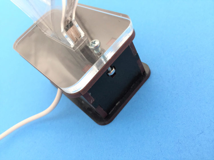
 N).
N).