Ian Jaucian (b.1986) is a Filipino visual artist and tinkerer who lives and works in the Philippines. He draws much of his inspiration from science, exploring its relationship with visual art through various media, which through the years have included paintings, sculpture, robots, kinetic and interactive installations.
It’s relatively cheap, quick, and easy to make LEDs glow wirelessly. The problem is usually making the machine look nice and durable for usable applications. This project utilizes a basic wireless electricity circuit and DIY crystal-growing techniques to come up with ambient lighting that can be used for both indoor and outdoor environments.
Originally developed for an interactive art installation, these crystals are made to light up when placed near transmitters buried under soil, sand or gravel.
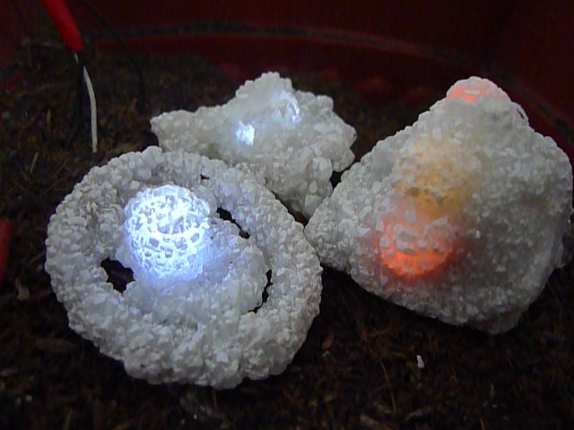
The finished project looks like a bunch of crystals that glow when placed on top of soil. What’s really happening is that LEDs inside the crystals light up wirelessly via magnetic induction coupling with transmitters beneath the soil.
The transmitter coil is basically a bifilar coil made from two wires joined at one end. I have gotten good results both from using magnet wire and solid core insulated copper wire. The number of coil turns in the transmitter and its ratio with the coil turns in the receiver affects the efficiency and range of the wireless electricity transfer. You should experiment with what will suit your purpose best, but for this tutorial I will be showing instructions for a particular build with a range of around 4 inches using #22 insulated solid core copper wire.
Take 2 strands of 4 meter-long wire and wind them in the same direction. For my coils, I began wrapping around a small screw mounted on a piece of plastic. Make sure the coil remains even and flat throughout the coiling process by constantly putting strips of tape to maintain the desired shape. You’ll end up with a pancake-shaped coil that is about the size of a CD. I suggest that you use wires with different-colored insulation because you will need to identify the ends of each wire.
Once you have your pancake coil, tape it up with masking tape or electrical tape to make sure it doesn’t uncoil. Take one of the ends of the wires in the inner part of the coil and connect it to the outer end of the other wire.
BUILDING THE OSCILLATOR CIRCUIT AND CONNECTING IT TO THE TRANSMITTER COIL
The oscillator circuit is composed of a transistor and a resistor. Build the circuit as shown in the image. Put a heat sink on the transistor because it will heat up! In this build, I used a TIP31C transistor. As you can see in the schematic, I used two 470ohm 5w resistors in parallel. Using a single resistor will work but the transistor may be more prone to heating this way.
The part of the transmitter coil where the 2 ends are joined connect to the positive lead of the DC powersupply. One of the free ends of the pancake coil connects to the transistor’s collector, the other one connects to base.
Take your magnet wire (I used #28) and make a single coil composed of 40 turns. The diameter should be between 1 to 1.5 inches. As a guide, you can wind the wire around a medicine bottle or anything in that size range. Remove the coil from the bottle and tape to secure the coil to make sure it doesn’t unwind. Strip off the insulation from the two ends of the magnet wire coil using a cutting knife. Connect an LED to the receiver, soldering the leads to the bared tips of the coil. You can connect more than one LED to the receiver.
Once you have the transmitter and receiver assembled, it’s time to connect to your power supply and test your wireless electricity circuit! I used a 3A 6v DC supply, but anywhere between 3-12v can be used. You can even use batteries to power the device.
When you put the receiver close to the transmitter, the LED should light up. If it doesn’t, try flipping the transmitter coil or receiver coil around.
The transmitter creates an oscillating magnetic field that the receiver coil “picks up” and converts to alternating current which in turn makes the LED glow.
The power transmitted increases as the distance decreases. More amps and more volts also lead to more power and range (as well as heat). The number of coil turns in both the receiver and transmitter also affect the performance of the machine. The type of wire used will also have an effect. Experiment with these different factors to optimize the circuit for the desired behavior and geometry.
Once you are done with the wireless LED, the next step is to create a nice-looking hard shell for it. We will be growing borax crystals around the receiver.
Prepare your receiver for crystal growth by coating it in an adhesive of your choice (spray adhesive is best but you can also opt to brush a liquid glue) and then coating it with borax powder. Let this dry for 1-2 hours.
When the receiver is dry, it is time to create a supersaturated solution of borax by mixing borax powder into hot water. The water should be as hot as possible without reaching boiling point. Gradually add borax while constantly stirring the solution. Stop adding powder when the borax doesn’t dissolve in the water anymore and you see the powder settling on the bottom of the container.
Tie one end of a piece of wire or string to the receiver then attach the other end to a rod that is longer than the diameter of your container. Place this on top of the container of supersaturated borax, making sure that the coil is at least an inch away from the borders of the container. Cover the solution with cling wrap, plastic or place it somewhere that will stop any dust from contaminating the solution as it cools.
The amount of water and borax as well as the temperature of the solution really depends on the container you will be using. The container should be large enough so that the crystals that grow will not touch the borders of the container. Crystals will grow best in a glass container, but some glass may crack when subjected to high temperatures. I prefer to use plastic containers because it is easier to recycle the borax that builds up on the container’s borders.
After around 2 hours, crystals will begin to form. The longer you wait, the larger the crystals will grow. Sometimes it takes a whole day to get the desired results. If you want even bigger crystals, you can place the already-crystallized receiver coil into a new batch of supersaturated borax solution. The great thing about borax crystals is you can always dissolve them in hot water to recycle them. This is useful when you plan to make a lot of crystals and want to reuse the unwanted crystals that form in your container’s borders.
Make as many crystals as you want and use different colored LEDs!
Since we are planning to bury the transmitter under soil, we have to waterproof it. The bifilar coil will still work even if it’s wet, but it should still be protected so that the insulation of the wires does not get brittle and make the copper prone to corrosion. One way to do this is by sandwiching the transmitter coil between 2 sheets of acrylic and sealing the edges with silicone, leaving only a tiny gap for the wires that go to the power supply and the oscillator circuit. You may also use softer plastic material to cover the coil (such as a plastic envelope or tarpaulin). The material you use will depend on your application; use more rigid material if the transmitters will be buried in soil that people will step on.
The oscillator circuit may not get wet, so either place it above ground or encase it inside a plastic box before burying it. I used a plastic box from the electronics store to encase my circuit. The power supply must also be placed above ground.
Once waterproofed, you can now bury your transmitter underground.
The steps described above will give you a crystal that glows when the transmitter under the soil is within range. The brightness will depend on the coils’ proximity to each other. In the video, you might notice that the crystals dim and brighten even without changing their distance. This was achieved by adding a microcontroller and another transistor to the transmitter circuit. The transistor’s base is connected to a PWM pin on the microcontroller.
With the following code, you can control the voltage transmitted and dictate how you want the lights to behave. The sample code makes the lights gradually dim and brighten for a “breathing” effect.
int volt = 0; // variable for the dimming behavior
void setup() {
// initialize digital pwm pin 10 as an output. The transistor base connects to pin 10.
pinMode(10, OUTPUT);
}
void loop() {
for (volt = 0; volt <= 255; volt += 1) { // goes from min to max voltage // in steps of 1/255 analogWrite(10,volt); // pwm value “volt” delay(10); // determines speed of action } for (volt = 255; volt >= 0; volt -= 1) { // goes from max to min voltage
analogWrite(10, volt);
delay(10);
To increase the surface area of the project, you can either make a larger transmitter coil or you can connect multiple coils together.
I’ve found that connecting coils in series is more efficient that connecting them in parallel. The following diagram shows how the coils can be connected in series. Of course the more coils you add, more power is needed and this makes the transistor hotter. Experiment by using different power supplies, transistors, heat sinks and cooling mechanisms.
The crystal lights are quite sturdy and will last a long time. However, they may lose some transparency depending on the humidity and heat of the environment. Their surfaces may become opaque white, especially if you happen to live in a tropical region. One way to prevent this is by spraying clear acrylic paint onto the crystals. Personally, I like to wait until the crystals lose some transparency before putting the protective coat because this makes them look more like natural rocks.
Ian Jaucian (b.1986) is a Filipino visual artist and tinkerer who lives and works in the Philippines. He draws much of his inspiration from science, exploring its relationship with visual art through various media, which through the years have included paintings, sculpture, robots, kinetic and interactive installations.
When you buy through links on our site, we may earn an affiliate commission.
Our websites use cookies to improve your browsing experience. Some of these are essential for the basic functionalities of our websites. In addition, we use third-party cookies to help us analyze and understand usage. These will be stored in your browser only with your consent and you have the option to opt-out. Your choice here will be recorded for all Make.co Websites.
Allow Non-Necessary Cookies
Escape to an island of imagination + innovation as Maker Faire Bay Area returns for its 15th iteration!
Buy Tickets today! SAVE 15% and lock-in your preferred date(s).