PAT PETERS is a software developer living in Council Bluffs, Iowa, with his wife, Christine, daughter, Eleanor, and two cats. In his free time, he teaches brass instrumental music lessons and programming classes at the 402 Arts Collective in the Omaha metro area. He also likes running, woodworking, and playing with his daughter.
Ever since I was 8, I’ve loved Harry Potter and the world that J.K. Rowling built with her books. I always related to Harry’s friend in the book, Ron Weasley, and I especially loved that Rowling tied the wizarding world into the real world.
this project is from the latest issue of Make: Magazine. Get yours now!
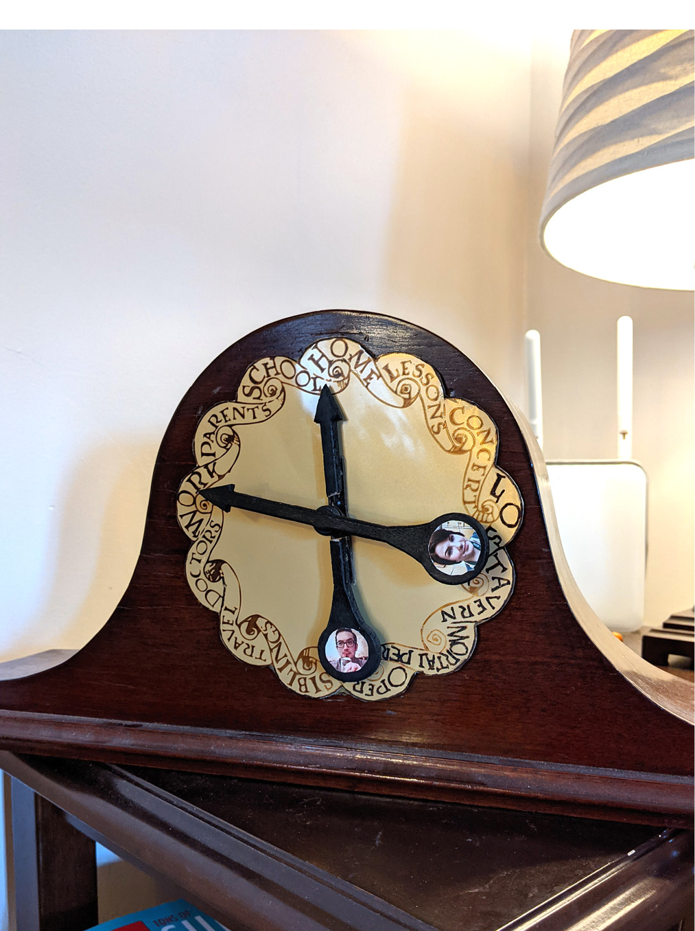
I wanted to bring a piece of that world into my own (while also geeking out with Raspberry Pi and GPS), which led me to re-create this famous prop from the book. This project is an Internet of Things Location Clock (or Whereabouts Clock, or Weasley Clock). Rather than having two hands that give you the time of day, this clock has a hand for each member of your family or group, and moves the hand to point to wherever that person is in the real world! My clock, for example, has two hands (for my wife and me) and shows locations for Home, School, my Parents’ house, our favorite bar, the opera house (we volunteer there), etc.
The Location Clock runs on a Raspberry Pi mini computer, which subscribes to an MQTT broker — a server for routing messages in the MQTT internet protocol. Our phones send a message to the broker anytime we cross into or out of GPS waypoints we’ve set up in the OwnTracks phone app, which then triggers the Pi to run a servo that moves the clock hand to show our location. And the Node-RED programming tool made it easy to automate without writing any code.
I’ve seen a couple different approaches to this clock idea, but I especially valued those of Allie Fauer, and Alya Amarsy. Here’s how I made mine.
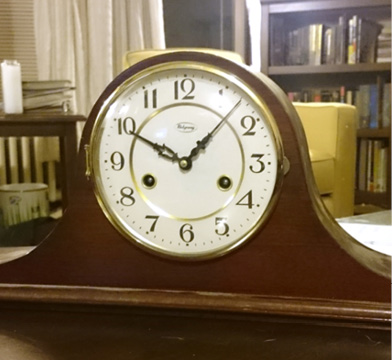
I wanted to give my Weasley Clock an authentic, old-fashioned look, like it’s been in the family for a while. On Craigslist, I eventually found an old-fashioned mantel clock that had broken down and was beyond repair.
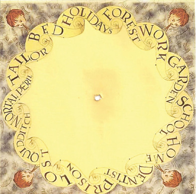
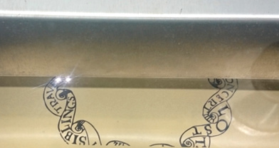
The clock face was the one piece I knew exactly how I wanted to look. I admit, my Photoshop skills aren’t quite up to snuff to make this from scratch, so I surfed the interwebs and found a design pattern I liked, from this artist on weebly . I downloaded her JPEG (above), imported it into Photoshop, and cut out the clock face.
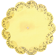
Next I had to find the Harry Potter-styled type font, so I could replace the destinations with what I wanted.
I converted my Photoshop document to a vector, then made an Adobe Illustrator vector to work with.
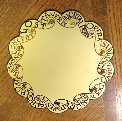
I wanted the clock to look antique, so I decided to etch the design onto metal. You can take several different approaches here. The easiest was to etch the design with a CNC laser engraver. I originally bought a sheet of solid brass but the laser wasn’t strong enough to etch it. Then I found an alternative: AlumaMark is thin, flexible aluminum sheeting that’s designed for marking with lasers. I took my Illustrator file to the Omaha Do Space, and “etched” my design with their laser cutter.
Lastly, I cut the face out from the metal sheet by hand — first a rough circle using a jigsaw, then a little more detail work with some tinsnips — and I had my clock face.
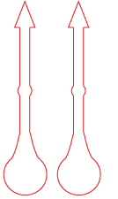
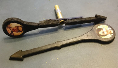
I designed the clock hands in Photoshop (above), converted them to a CNC-friendly vector graphic in Adobe Illustrator (below),
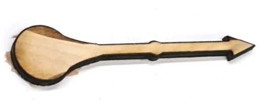
then laser-cut them out of ¼” birch plywood.
But I’d forgotten to add holes in the original design, and when I tried to drill them the brittle, scorched plywood broke apart. To work around this, I cut a bit of leftover acrylic to the same width, and drilled the hole through that. I then glued the broken clock hands onto the acrylic, and painted the whole assembly with black spray paint.
Finally, I printed out two small pictures of myself and my wife to attach to the clock hands.
This part was by far the most challenging: How to get the individual clock hands to move freely of their own accord while remaining stacked on top of each other?
I spent a good deal of time looking at previous whereabouts clocks for inspiration. The majority used display screens to show clock hands, or light-up displays to show the different locations. I really wanted my clock to have moving hands, to give it a real, antique look.
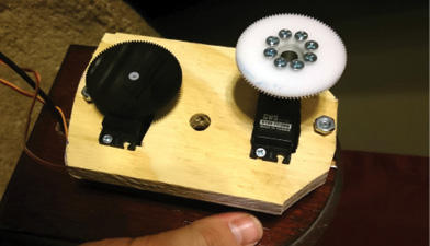
I finally found a design, used by two other fellow magic clock makers, that relies on tubes of varying circumferences stacked inside each other and controlled by specialized sail-winch servos (used for R/C sailboats). The thing I really like about this design is that you can add as many hands as you like, until you run out of room for servos! I used two GWS model S125 1T 2BB servos that provide accurate, full 360° rotation (most servos only have a range of about 180°); I found them on AliExpress. You can find the K&S Hobby brass tubes, 9/32″ and 1/4″ diameter, at any hobby store, R/C store, or online.
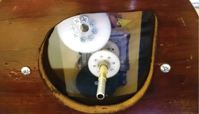
I cut a mounting block for the servos and tubes out of a scrap of ½” plywood, and attached it to the clock’s back door. Each servo has a large gear mounted on its shaft; the top gear is connected to a spacer hub to stagger the two. The tubes fit into the hole in the middle of the block.
On each tube is a smaller gear hooked up to a screw-on gear hub, so that when the servo turns, the tube rotates.
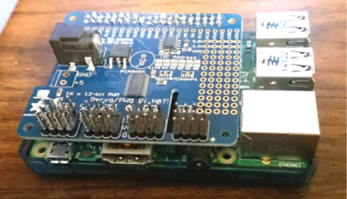
The Raspberry Pi I’m using has only one GPIO output pin that can supply a full 5 volts of output, but I need 5V to drive each servo. Thankfully, Adafruit makes a Servo Hat that can supply the additional outputs for the servos, and it fits right on top of the Pi.
You control servos with pulse-width modulation (PWM). Without getting too much into the nitty gritty, PWMs are signals sent at a steady pulse in whatever frequency you need to control electronics like LED lights and servos. By changing the length of time between the high and low signals, we can control how far the servo’s shaft turns, which then points the clock hand wherever needed.
Using the Adafruit library, I set a bit of Python code for each hand position I need, then I call these from a system command node in Node-RED. The Python code treats the PWM instances as their own objects, so every time I need to set a hand’s position, the code will:
• Create a new PWM object
• Set the exact frequency of the PWM object
• Set when in each pulse the signal should change from low to high and then back from high to low
• Close the PWM object, so the clock hand stays in whatever position I need.
You can see a video of me running a test script and you can download my code for one of the hand movements, location_clock.py, based on the example code provided by Adafruit.
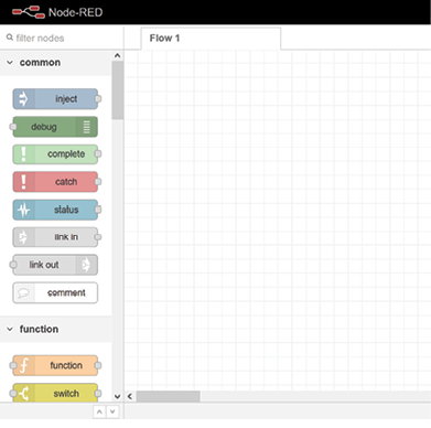
Node-RED is an open source Node.js programming tool that enables you to set up some fairly advanced programs and workflows without writing any code. It has an extensive library of “nodes” you can use to automate actions based on events such as an incoming text or email, a time of day, or (in our case) an incoming message from an MQTT broker.
Node-RED might already be installed on your Raspberry Pi OS, but older versions can be terribly out of date and insecure. To install the newest versions of Node.js, npm, and Node-RED all at once, type the following into your terminal on the Raspberry Pi and hit Enter:
Once you have Node-RED installed, start up the service by running the following command in the terminal:
node-red-start
Once the service is up and running, you can either go to 127.0.0.1:1880 in a browser on your Raspberry Pi, or if you’re on the same internal network as your Pi, you can open a browser and type in the Pi’s IP address on port 1880 to go to the Node-RED Setup screen. So, for example, if my Raspberry Pi has an internal IP address of 192.168.0.100, I would go to http://192.168.0.100:1880 to navigate to the setup screen.
SETTING UP AN MQTT BROKER
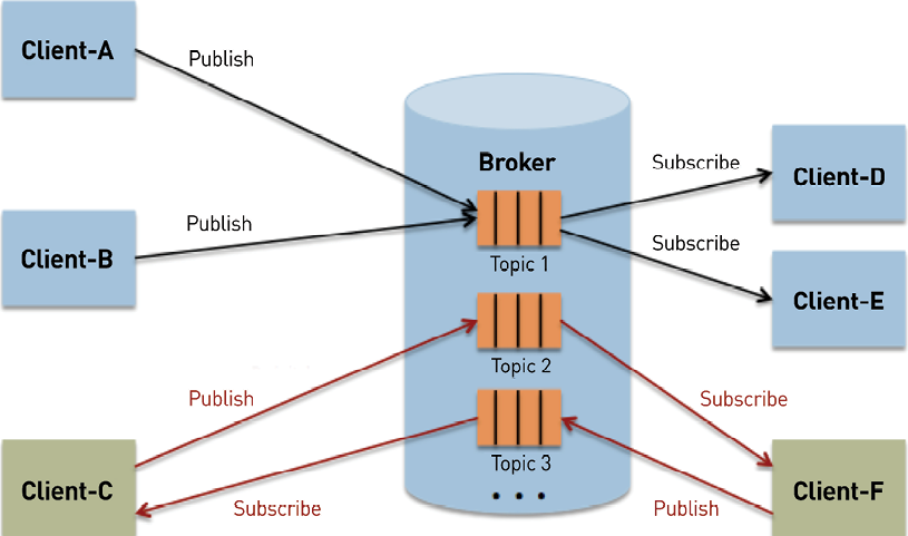
MQTT (Message Queueing Telemetry Transport) is a popular messaging protocol that uses a publisher/subscriber model for sending machine-to-machine messages on spotty connections. The main thing I like about it is the amount of documentation out there about it, and that it is very lightweight on data usage. I have it running on my phone 24/7, and it barely uses 1 megabyte of my 4G data per month!
Before you can send data via MQTT, you need to set up an MQTT broker to route messages. An MQTT broker acts as the server that you either publish messages to, or subscribe to, in that you receive any messages from a given publisher. MQTT clients (like the phone app you’ll install to send GPS coordinates) publish their messages to topics — different channels on the broker to which a client can publish or subscribe.
There are several different options for setting up an MQTT broker:
• Self Hosted: You set up MQTT broker software on a server you control and operate; Mosquitto is a popular option.
• Paid Service: You pay for an MQTT connection where you control the topics and messages you publish/subscribe to; CloudMQTT is one example.
• Open Broker: You post to a free and open public MQTT broker such as iot.eclipse.org. Great for testing but not secure!
Each type has its benefits and downsides.
Open Broker
The first category is a public, open broker that anybody with an MQTT client can use to publish messages and subscribe to topics.
WARNING: Open brokers are not secure. They’re very nice for testing that your Node-RED flow is set up correctly, but should not be used as a normal broker for this project! You’re posting your personal GPS coordinates and waypoints, which is not the sort of thing you want to post to a broker that anyone can access.
One of the most popular open brokers is test.mosquitto.org. For testing my connection to the broker, I either download an MQTT client or use a web MQTT client like MQTT Lens. Steve’s Internet Guide has a great write-up on how to download and use it and generally has a ton of fantastic information related to MQTT and Node-RED. I used this site quite a bit while getting familiar with this protocol!
Once you’ve tested connecting to an open broker with an MQTT client, you can then test setting up the broker in Node-RED and make sure you can subscribe to a topic within Node-RED (I’ll say more about that a little further down in this guide).
Paid Service
You pay a subscription fee in order to send and receive messages via MQTT. The downside is obviously you have to pay a fee, though for the size of this project (using only 1–4 clients, a single broker, and a limited amount of messages), you should be able to use the lowest-cost option in almost any paid MQTT service I’ve seen yet.
To demonstrate this setup, I’m going to use CloudMQTT as the paid service. Their current cheapest plan ($5 a month) is more than enough to handle the amount of users and messages we’ll be setting up!
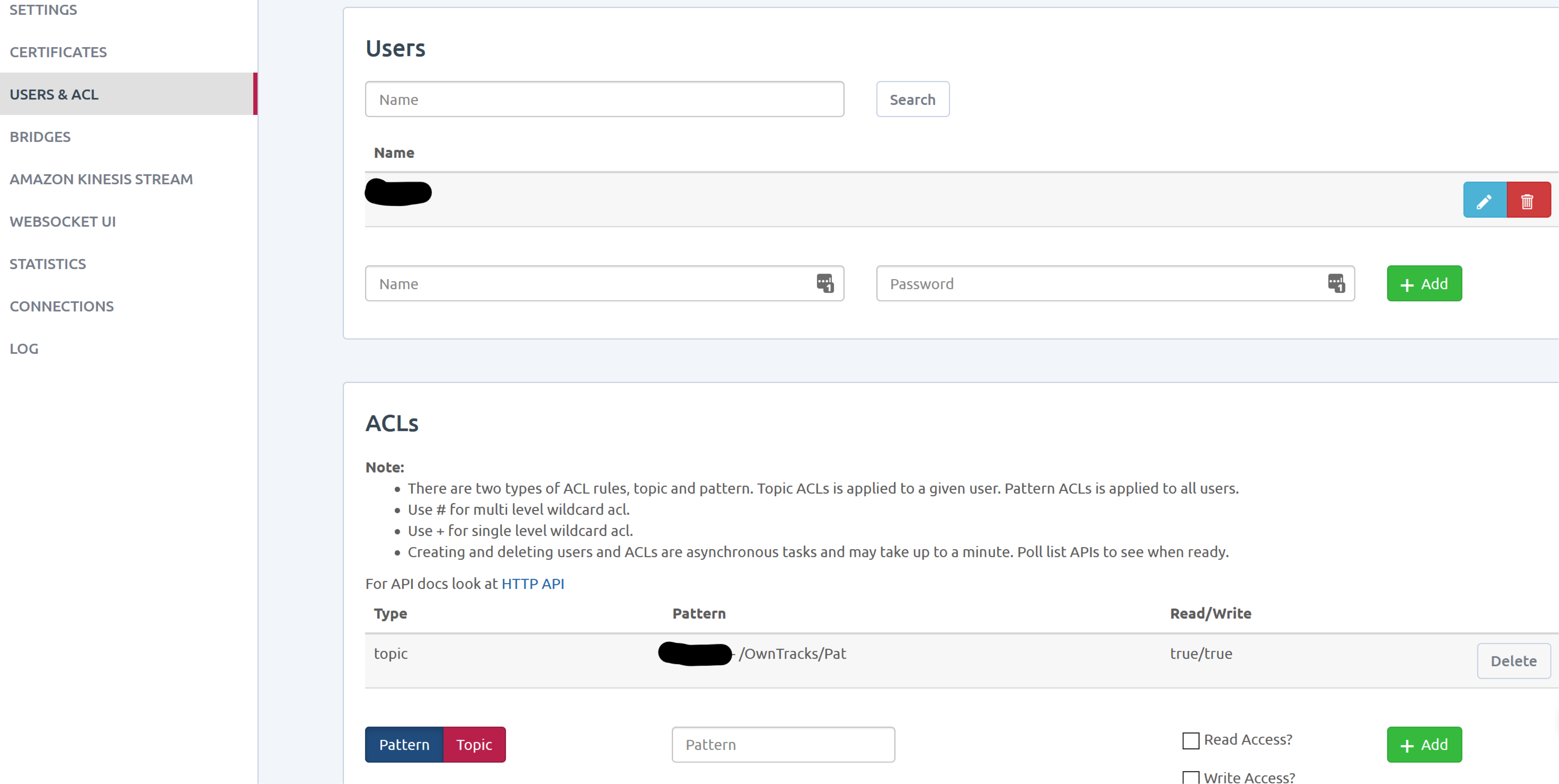
To use CloudMQTT, you’ll have to create an instance and select a payment plan. Once you name your instance, you can create a new user and assign that user an access control list (ACL).
In the image above, I created a user (blacked out the username) and assigned that user to the MQTT topic /OwnTracks/Pat. Since there aren’t any other ACLs associated with this user, that means this user account can only publish and subscribe to the topic /OwnTracks/Pat/. You’ll have to create at least one account that you’ll eventually use to publish messages from your phone, and then you’ll need one account (could be the same account) for the Raspberry Pi to subscribe to the MQTT topic you created in order to receive the messages from your phone.
After you create the user and ACL, you can go to the Details panel of your CloudMQTT account, which should give you all the connection information you’ll need, including the server address, port to connect with, and additional Client information. You’ll want to keep this information handy when setting up your phone to connect to the broker, and when setting up the Raspberry Pi to connect to the broker.
Self Hosted
Probably the most popular software for hosting your own MQTT broker is the open source broker Mosquitto, a package maintained and hosted by the Eclipse Foundation. There are a plethora of guides and tutorials on setting up your own Mosquitto MQTT broker. This one from Digital Ocean is probably my favorite, since it also includes instructions on setting up free SSL certificates (so that you can encrypt your connections) through Let’s Encrypt.
After you set up the MQTT broker that works for you, you’ll want to create an MQTT user for each person who’ll be represented on the location clock, and one for the Raspberry Pi to use as well. MQTT doesn’t require authentication for publishing or subscribing out of the box, but it’s very easy to set up authenticated topics so that only authenticated users can publish or subscribe to specific topics.
Keep all this user login information handy — you’ll use it again when you’re configuring OwnTracks and Node-RED to connect to the MQTT broker.
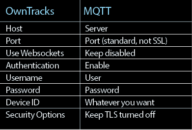
For GPS services on this project, I decided to use OwnTracks, a free app for iOS and Android devices. It’s very easy to set up and start your MQTT connections.
To set up OwnTracks on Android phones or iPhones, follow the instructions I originally published on Instructables. Here’s a quick list of what goes where between MQTT and OwnTracks:
Once you have the correct settings put in, bring up the Websocket UI on your MQTT console. If everything is set up correctly, you’ll get a new MQTT message when your phone connects to your MQTT broker and updates its location.
Now that you’ve connected OwnTracks and your MQTT broker, you can set up “geo-fence” areas that will be the trigger points for when the clock hands should turn.
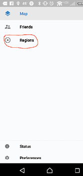
On the OwnTracks main page, go to the menu and select the Regions option. When the region window comes up, hit the plus sign at top right to add a new region.
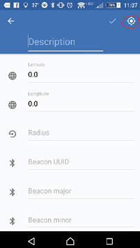
Give the region a name in the Description field and keep track of it — you’ll have to reference it when you get to the setup on the Raspberry Pi.
You’ll need to also supply your latitude and longitude coordinates. The newer versions of the OwnTracks app for iOS and Android link to Google Maps so that you can input an address and pull the lat and long coordinates from there.
You’ll also have to specify the radius of the region (in meters). The region can be as big or small as you want. One of the regions I set up is the entire city of Chicago!
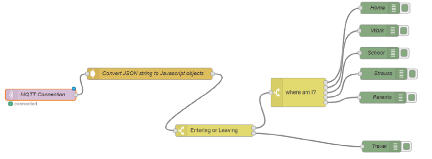
The Node-RED flow for this setup is fairly simple, but took me a good while to figure out. The flow starts with the connection to the MQTT broker with the MQTT node. This node is pretty self explanatory, but make sure your MQTT node is subscribed to the correct topic. For my clock, I wanted the hands to move only during OwnTracks transition events (right when you enter or leave one of the waypoints). OwnTracks creates a separate topic for these events in the format MQTT-topic/event, so for example, mine was owntracks/userID/deviceID/event). As long as you subscribe to that topic with your MQTT node, you should only pick up messages when you enter or leave one of your waypoints.
When the MQTT node is triggered from the broker, a JSON string is sent to Node-RED with all the necessary info from your device. JSON (JavaScript Object Notation) is just a data-interchange format that organizes all your content in a manner that’s easy to read both for you and a machine. Here’s one of the JSON strings that was sent from my broker:
For my clock, really the only parts of this string I need are the location (“desc” for description) and whether I’m entering or leaving (“event“). I can’t really do a whole lot with just a string, so I need to convert the string into an array of JavaScript Objects.
To convert this string into objects, use the JSON function node that comes standard with the node-red-pi installation. This parses through the JSON string for you, and formats each string into a group of objects.
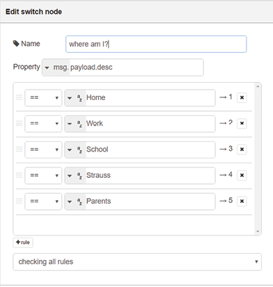
For this setup, the JSON string parser feeds directly into a switch node. This node takes the newly created object msg.payload.event and checks whether that object is set to leave or enter. If it’s set to enter, then the flow is directed to a second switch node that checks the value of the object msg.payload.desc; this switch node then feeds into whichever location matches up with the desc object value so that it can move the hand.
If in the first switch node the msg.payload.event object is set to leave, then the flow immediately moves to setting the clock hand to “Travel”. I then have Node-Red run a system callout (like if I was calling something from the terminal) that runs a Python script, and passes a variable of the msg.payload.desc location. My Python script picks up the variable and knows where to move the clock hand based on that.
When the flow moves the clock hand to “Travel,” a trigger node is also activated that counts for 6 hours. If msg.payload.event hasn’t been updated (from when I enter another known location) after 6 hours, then the flow activates the servo to move the hand to “Lost” and sets another trigger. The second trigger counts for 24 hours while waiting for an updated msg.payload.event. If it doesn’t receive that update in 24 hours, it finally moves the hand to “Mortal Peril.” Bit of a gag if I have to go on a trip for work or if I turn my phone off for a few days, but other than that, should be pretty clear!
With the clock hands set in place, and the Python code loaded up, my Weasley location clock is all set. Off we go into the wizarding world, with our magic whereabouts clock keeping tabs on everyone in the family.
I hope you’ll give this project a try, and share your improvements.
PAT PETERS is a software developer living in Council Bluffs, Iowa, with his wife, Christine, daughter, Eleanor, and two cats. In his free time, he teaches brass instrumental music lessons and programming classes at the 402 Arts Collective in the Omaha metro area. He also likes running, woodworking, and playing with his daughter.
When you buy through links on our site, we may earn an affiliate commission.
Our websites use cookies to improve your browsing experience. Some of these are essential for the basic functionalities of our websites. In addition, we use third-party cookies to help us analyze and understand usage. These will be stored in your browser only with your consent and you have the option to opt-out. Your choice here will be recorded for all Make.co Websites.
Allow Non-Necessary Cookies
Escape to an island of imagination + innovation as Maker Faire Bay Area returns for its 15th iteration!
Buy Tickets today! SAVE 15% and lock-in your preferred date(s).